KNEC KCSE Past Papers Electricity 2014
KCSE Past Papers Electricity 2014
3.20.1 Electricity Paper 1 (448/1)
SECTION A (48 marks)
Answer all the questions in this section.
1. a)List the three classes of materials according to their electrical conductivity and for each class give one example. (3 marks)
b) State the meaning of the term career. (1 mark)
2 a) List four characteristics of an entrepreneur. (2 marks)
b) For each of the following activities, state one safety precaution to be taken when: (2 marks)
(i) removing a 470 uF/240V capacitor from a television set circuit during repair;
(ii) handling rotating parts of electrical machines.
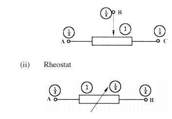
3 With the aid of graphical symbols, describe the difference between a potentiometer and a Rheostat. (5 marks)
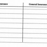
4 The average daily power consumption of a domestic consumer is as follows:
– Lighting O.5kw for 6 hours
– Water heating 3.0kw for 2 hours
– Cooking 5.0kw for 2 hours
– Other appliances 3.5kw for 3 hours
.a) Determine the daily consumption in kWh. (3 marks)
b) If the monthly standing charge is Ksh.100.00. calculate the bill for a month of 30 days. (3 marks)
5 a) State four factors that detennine the strength of an electromagnet. (2 marks)
b)Figure 1, shows the direction of force on a current carrying conductor in a magnetic field. Sketch the magnetic flux lines to create the force. (2 marks)

6. From the circuit shown in figure 2 calculate the values of:

(a) E
(b) R2
7 (a) Name four accessories used in domestic lighting installation.
(b) State one difference between MIMS and PVC sheathed cables.
8 a)Name two types of D.C generators.
(b) With the aid of a diagram, describe the operation of a simple A.C. generator.
9 (a) Perform each of the following number conversions.
(i) 1011012 to decimal
(ii) 46 H] to binary
(b) Figure 3, shows a symbol of a logic gate.

State the effect on voltage across RL when: (2 marks)
(i) Zener diode is shorted.
(ii) Zener diode open..
10 Figure 5, shows orthographic views of a block, drawn in first angle projection.
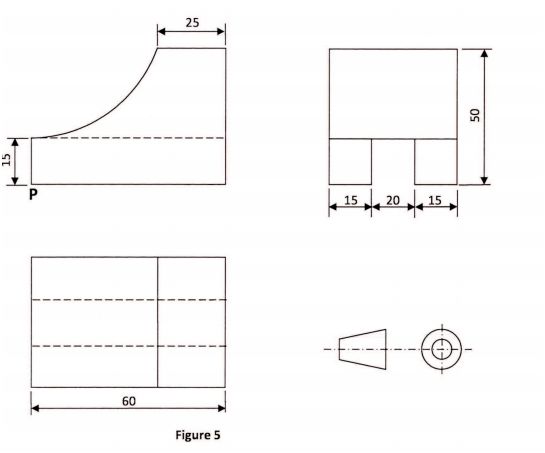
On the isometric grid paper provided, draw the block in isometric projection with P as the lowest point. (5 marks).
SECTION B (52 marks).
Answer any four quesliuns from this section, in the spaces provided. 11 (a) With reference to Sinusoidal waveforms, explain each of the following terms: (3 marks).
(i) Amplitude;.
(ii) Period;.
(iii) Frequency..
(b) A Sinusoidal voltage trace displayed on an oscilloscope has peak to peak voltage of 24 V and a period of 40 ms.
Draw the waveform and calculate: (10 marks).
(i) Frequency;
(ii) Average value;
(iii) RMS value.
12 a) With the aid of a labelled diagram, explain the operation of a split-phase AC motor. (8 marks)
b) An ideal transformer is used to step down 480 V to 240 V. The 240 V output is connected to a 24 KW resistive load.
Determine the: (5 marks)
(i) load current;
(ii) input current;
(iii) transformer ratio.
13) a) Draw a wiring diagram of a final circuit of one lamp controlled from three different points. (4 marks)
b) With the aid of a labelled diagram, explain the operation of a switch start fluorescent lamp. (9 marks)
14 a) Describe each of the following processes of making a permanent magnet: ‘ ‘ (4 marks)
(1) heating;
(ii) stroking.
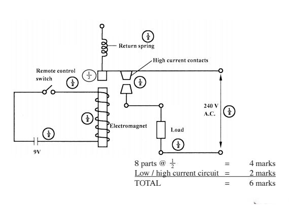
b) With the aid of a labelled diagram, explain how a relay operates a high current load. (9 marks)
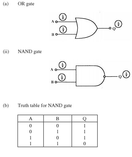
15 a) Draw and label a schematic symbol for each of the following two input logic gates. _ (3 marks).
(1) OR (ii) N AN D.
b) Construct a truth table for a two input NAND gate. (4 marks).
An electric kettle suddenly stops heating water yet there is power in the socket outlet..
c) Outline the procedure for identifying the possible faults using an ohmmeter. (6 marks).
3.20.2 Electricity Paper 2 (448/2)
1 EXERCISE 1
Use the circuit, equipment and component provided to perform the following tasks.
(a) Connect the resistors labelled A across point X and Y of the circuit.
(b) Set the stopwatch to zero.
(0) Press switch S until voltage reading settles at about 1OV.
(d) Release push button switch S and time the duration it takes for the voltage to drop to about 3-7 V and record the time in Table 1.
Table 1

(e) Repeat tasks (a) to (d) for each of the resistors B, C, D and E. (12 marks)
(D Use schematic symbols to draw the circuit and label the components. (6 marks)
(g) From the results obtained, calculate the value of resistor labelled E. (2 marks)
2 EXERCISE 2
Using the materials, tools and equipment provided, fabricate the candle stand shown in figure 1. Its dimensions are given in the layout. (20 marks)

3 EXERCISE 3 Using the components, materials and equipment provided, perform the following tasks.
(a) Connect the circuit shown in figure 2 and let the examiner check your work. (6 marks)

Figure 2 For each voltage obtained, measure and record the corresponding current values. (5 marks)
(c) Plot a graph of current against voltage. (6 marks)
(d) From the graph:
(i) determine the resistance when the voltage is 1.3 V;
(ii) give a reason for the shape of the graph. (3 marks)
4 EXERCISE 4
Using the pre-fabricated circuit provided in figure 3, perform the following tasks:—
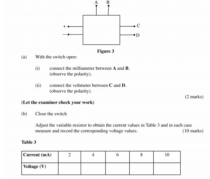
Figure 3
(a) With the switch open:
(i) connect the milliameter between A and B.
(observe the polarity).
(ii) connect the voltmeter between C and D.
(observe the polarity).
(Let the examiner check your work)
(b) Close the switch (2 marks)
Adjust the variable resistor to obtain the current values in Table 3 and in each case measure and record the corresponding voltage values. (10 marks)
Table 3 (c) (i) Plot the graph of current against voltage.
(ii) Use the graph to determine the value of current when the voltage is 5. 5 V. (8 marks)
5 EXERCISE 5
Figure 4 shows a lighting circuit. Using materials, tools and equipment provided, instal the circuit such that the switch controls the lamp. (20 marks)

KCSE Past Papers Electricity 2014
4.20.1 Electricity Paper 1 (448/1) 1 (a) Classes of materials
(i) Conductor – silver, copper, gold, aluminium.
(ii) Semi-conductor – carbon, silicon, germinium.
(iii) Insulators – PVC, porcelain, rubber, mica.
(b) Career – profession or occupation chosen as one’s life‘s work. (1 x 1) = 1 mark
2. (a) Four characteristics.
– Self confident.
– Optimistic.
– Action oriented.
– Futuristic.
– Achievement motivation.
– Respond positively to challenges.
(b) (i) Discharge the capacitor by shorting the terminals (D guard against contact with any pan of the body.
(11) Be dressed so that no pal1 of the clothing may accidentally be caught up in the rotating part of the machine.
3. (i) Potentiometer.
Terminals
(a) W=Pt
=(0.5><6)+(3><z)+(3.5><3)+(5><2) Q)</z)+(3.5>
=29.5kwh Q)
(b) Cost of electricity
=(Z9.5kWh><7.0())><30 Q)
=6195Q)
= 100 + 6195 = 6295 (D
(6 x 1) = 6 marks
5 (a) – Number of turns. 3
– Amount of current.
– Type of core material
– Ratio of length to Width of coil.
(b)

– Lines ufflux around the conductor
– lines of flux around the conductor.
– Lines of flux between the magnets.
6. (a) (b) E:5+(2mA 21<)@
= 5 + 4 = 9 v
7. (a) – Lamp holders.
– Bulbs/tubes.
– Switches
– CCU.
(b) – MIMS sheathing is made of copper while PVC sheathing is made of PVC.
– MIMS has a good heat resistance while PVC cannot Withstand high temperatures.
8. . (a) – Separately excited.
– Shunt wound.
– Series wound.
– Compound wound.
(b)

– A loop of conductor is rotated between poles of a pair of magnets. GD The loop
is mounted in a such away that it is free to be rotated between the fields of the two magnets.
– If the loop is rotated and cuts the magnetic flux, an emf is induced @ in the loop.
– The two ends of the loop are connected to two copper rings called® slip rings which provide a path for the induced current to the external circuit.
2 marks
9 (a) (32><1)+(8X1)+(4X1)+(1×1)
: 32+8+4+1
=4O+5=451n
46
=1011102
(b) (1) NOR gate
69 69 Q3
b)

(c) (i) Zener diode shorted – Zero voltage across RL.
(ii) Zener diode open
– Increased voltage across RL.
10.

SECTION B
quantity.
11 a (i) Amplitude is the maximum value, positive or negative of an alternating
(ii) Period is the time taken by an alternating quantity to complete one cycle.
(m) Frequency is the number of cycles of an alternating quantity completed in a unit time.
(b) (i)

(ii) Average valL1
e, Vav :O.637><vmax
=0.637> = 7 .644 V</vmax
Peak values –
Wave form –
(iii) Rms value, VRMs = 0.707 >< Vmax
0.707 X12 = 8.484 V
2 marks
Total = 13 marks
12.
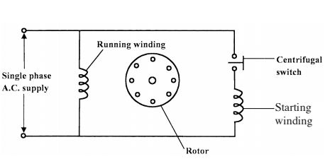
– A rotating field is achieved for starting purpose by having the motor with two stator windings in order to produce a phase difference between the currents in the two Windings.
– The method of switching the starting winding is by a centrifugal switch This allows the starting winding to be switched off before the motor reaches its normal speed – Once the motor reaches its normal speed, it runs with only one winding energized.
4 marks (b) (1) Load current 12:
_ 24000 _ _( 240 )_10OA
(ii) For an ideal transformer
Output power = input power G) = I2
Input current I2 = ( 2:380) = 50A G)
(iii) Transformer ratio
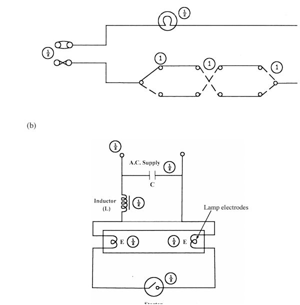
Operation
– When the supply is switched on with starter switch closed, current flows through inductor (L) and through lamp electrodes E.
– This initial currents heats the lamp electrodes in readiness for striking the lamp.
– The starting switch is now opened making a sudden interruption in the current fiowing through the inductor and causing a high voltage to be induced.
– The voltage starts a discharge between the two lamp electrodes and current rises rapidly due to the inductor.
– The starter switch is left open while the lamp is alight, the electrodes maintaining their operating temperature as long as they continue to pass the discharge current. 5 marks
14. (a) (i) Heating.
– A ferromagnet metal alloy is heated to bright red hot ® then allowed to cool in a powerful magnetic field.
(ii) Stroking
– This involves stroking a piece of hard steel with one pole of magnet along the length of metal piece. (D At the end of each stroke the magnet is lifted up and taken through a reasonable curve. The starting end takes the same polarity as the stroking pole of the magnet.
4 marks
(11) High current contacts Remote control Electromagnet Lnad – When the remote switch is closed. Current flows through the coil making it an electromagnet.
– The electromagnet attracts the armature which closes the circuit.
– The load in the controlled circuit then operates and when the switch is opened, the load stops to operate.
(b) Truth table for NAND gate
(c) – Inspect the top plug, cable and kettle for bum-out signs.
– Open the top plug ®and check for loose connections
– Check for fuse continuity.
– Check for continuity of cables/conductors.
– Remove the element and check continuity ® of the element.
6 marks
