KNEC KCSE Physics Paper 3 – 2014 Nakuru District Mock
2014 Nakuru District Mock
Physics Paper 3
1) Measure the diameter of the wire using the micrometer screw gauge…………………………….cm. (1mk)
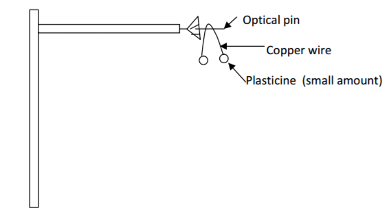
2) Set up the apparatus as shown in the diagram below
b) Bend the wire in the middle so as to make an angle of 40o. Attach the two small pieces of plasticine at both ends of the bend as shown in the diagram.
c) Place the bent wire on the optical pin and give a small horizontal displacement. Note the time for 10
complete oscillations and record in the table below.
d) Repeat the procedure above for other values of ϴ and complete the table below (8mks)
| Angle θ o | Time t for 10 oscillations (s) |
Period T (s) | Frequency f (Hz) =1/T |
f2(Hz)2 | cos (θ/2) |
| 40o | ………………. | ………………. | ………………. | ………………. | ………………. |
| 60o | ………………. | ………………. | ………………. | ………………. | ………………. |
| 80o | ………………. | ………………. | ………………. | ………………. | ………………. |
| 100o | ………………. | ………………. | ………………. | ………………. | ………………. |
| 120o | ………………. | ………………. | ………………. | ………………. | ………………. |
On the graph paper provided, plot a graph of f2 (y-axis) against cos (θ/2) (5mks)
(i) Determine the gradient S of the graph(3mks)
(ii) The equation for the oscillation of the wire is given by the formula:
Given that L 15cm find the value of Z. (3mks)
20 marks
Question 2
You are provided with the following apparatus:
- 3 dry cells, cell holder and a switch
- Nichrome wire 1m long mounted on a metre scale
- Resistor R 5
- A bulb
- Voltmeter
- Eight connecting wires one with a crocodile clip or jokey
Proceed as follows:
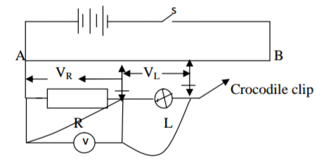
i) Connect the three dry cells in series with the switch and nichrome wire.
ii) Connect the resistor and bulb in series at the end A of the wire.
iii) Connect the voltmeter across the resistor R. Close the switch and check that the
reading on the voltmeter can be varied by altering the position of the crocodile clip
on the wire AB.
iv) Adjust the position of the crocodile clip to 40cm from end A. record the voltmeter
reading VR across the resistor R. v) Repeat this experiment using the table below.
vi) Disconnect the voltmeter and reconnect it across the bulb L without altering
anything else in the circuit. Record the voltmeter reading VL across the lamp.
vii) Repeat the experiment using the table below. (7mks)
| Length L(cm) | 40 | 50 | 60 | 70 | 80 | 90 | 100 |
| VR | …… | …… | …… | …… | …… | …… | …… |
| VL | …… | …… | …… | …… | …… | …… | …… |
viii) Plot a graph of VL against VR on the axis provided.(5mks)
ix) From the graph find the value of VR when VR = VL. Use this value and the value of
R given to calculate the current flowing in the bulb. (4mks)
x) Calculate also the resistance of the bulb. (3mks)
xi) Determine the slope of the graph at the point where VR = VL. (2mks)
20 marks
